The fuse switch built into this old-style Power Factor unit had failed in such a way that the rotary handle mechanism no longer functioned.
The unit was luckily fed via another MCCB in the LV panel so it was able to be isolated safely. The fuse switch was then removed and a new 200A load break switch was installed in its place using the original power cables.
A new interlocking handle and shaft were installed and then the unit was put back in service.
Unit replacement on baggage line at large UK airport.
Due to a change in the load, this existing single-stage 50kVAr unit was too large for accurate correction so it was to be replaced with a unit that still had a total kVAr output of 50kVAr but split into 4 smaller stages of 13.5kVAr.
Utilising the existing power cables and C.T cable the unit was swapped out with a standard FS100 PFC unit with built-in local isolation and the remote control relay was moved from the LV panel into the PFC unit itself for easier access.
This 100kVAr Power Factor Correction unit installed at a high street supermarket had not been fully serviced since its installation in 1992 and as such we recommend an ‘End of Life’ replacement for all components.
This FS style of PFC unit built by us at PFC Engineering is still in use today, however with a more updated style. This meant that our workshop was able to build and pre-test the whole tray assembly and then one of our site engineers was able to replace the old ‘SBA Tray’ like for like.
The new SBA tray assembly consisted of all new 480V rated Frako capacitors, IMO MC32 soft switching contactors and subfusing.
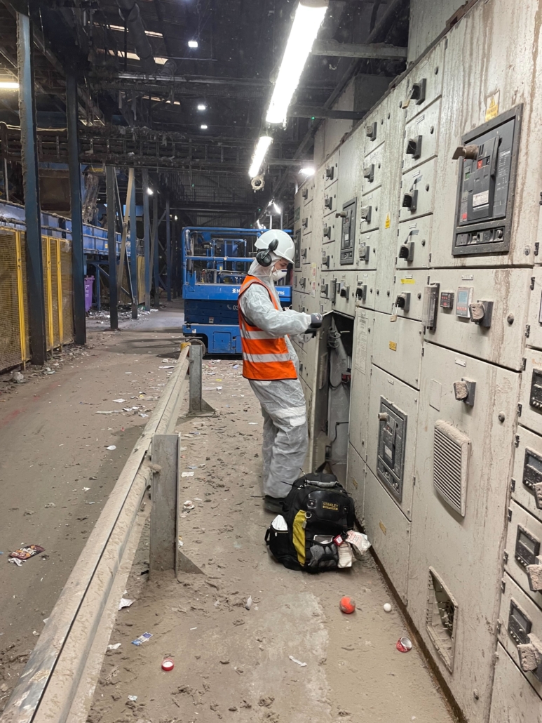
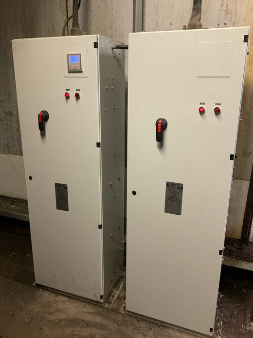
A recent installation of two Power Factor Correction units at a large recycling facility in north London.
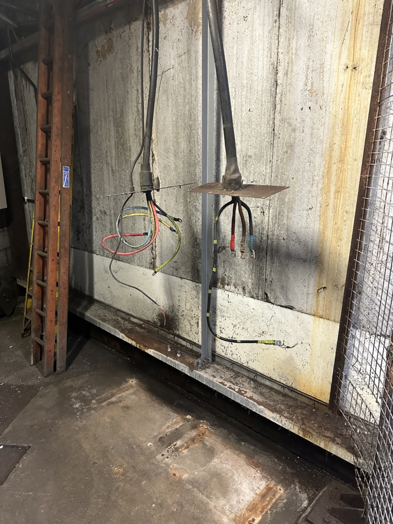
Due to the nature of the site, the switchgear was extremely dirty and the original Power Factor Units installed, one stand-alone unit and one panel-built unit, had to be disconnected and removed ready for the new equipment to be installed.
The larger of the two panels was a fully detuned 400kVAr FSi Deep PFC unit with 8 stages of 50kVAr, each with its own 189Hz detuning reactor, soft switching contactor and sub-fusing.
The smaller unit was also a fully detuned 250kVAr FSi PFC unit with 5 stages of 50kVAr each with its own 189Hz detuning reactor, soft switching contactor and sub-fusing.
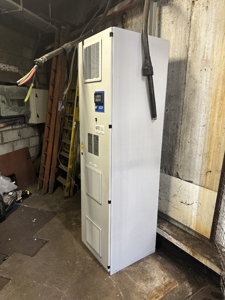
Once the old equipment was removed and the new units positioned, additional cable trunking was installed for cable management and a shutdown was scheduled for final connections.
Finally, the area was cleaned up and the units were commissioned. All the works were carried out over 3 days by 2 of our engineers with minimal disruption to the site.
https://www.pfc-engineering.com/wp-content/uploads/2024/03/Recycling-Plant-1-scaled.jpg25601920Ben Wallacehttps://www.pfc-engineering.com/wp-content/uploads/2021/10/PFC-Logo.pngBen Wallace2024-03-19 10:00:202024-03-15 14:03:24PFC Unit Install at Recycling Centre
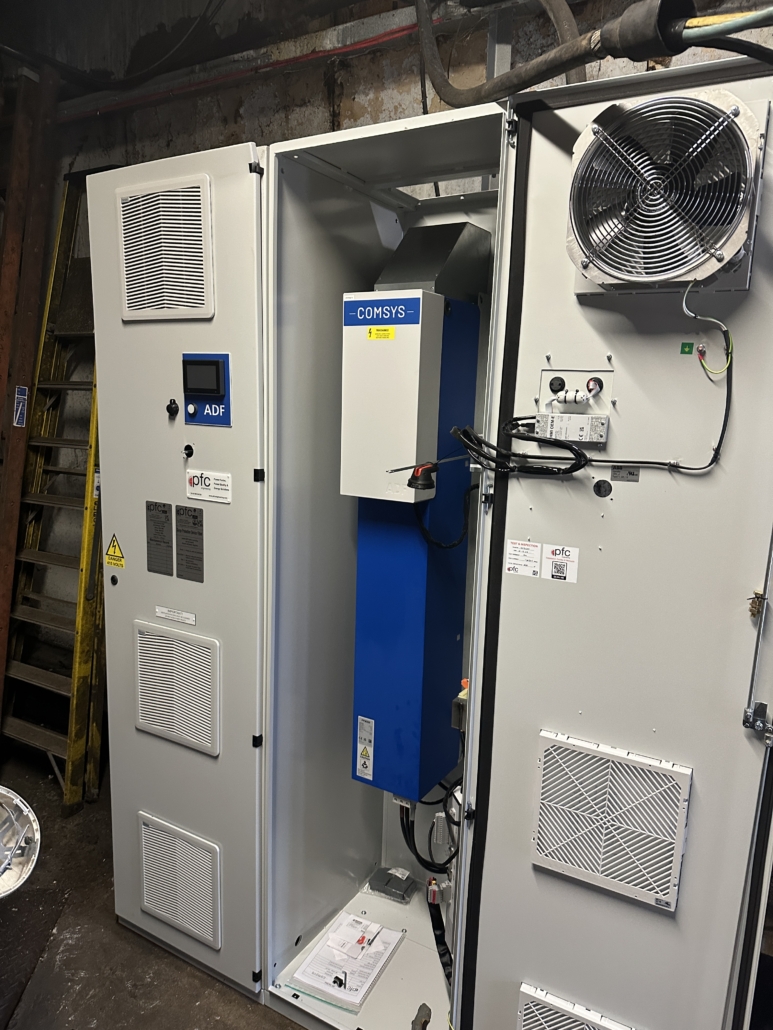
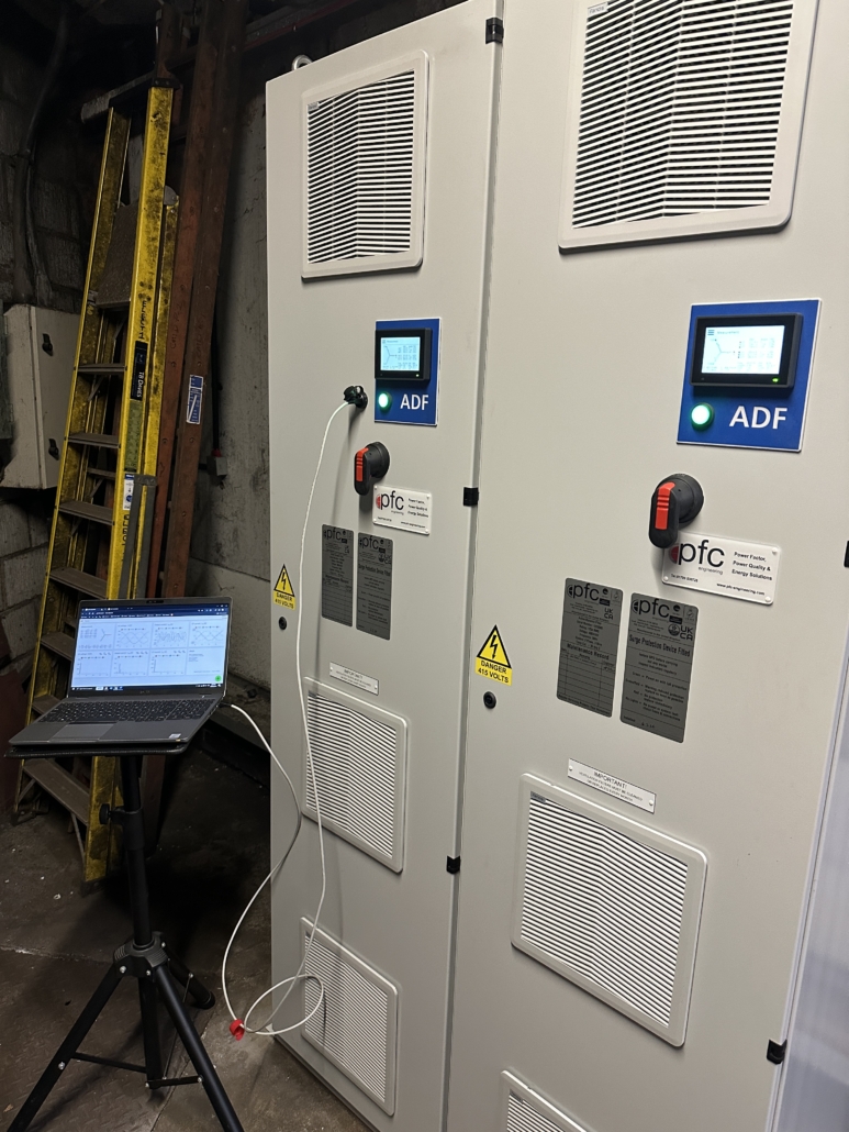
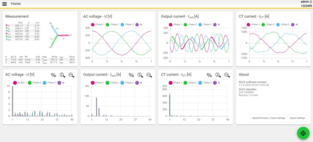
Harmonic levels at a large grain storage and drying factory had, over the past few years, crept slowly up in distortion eventually leading to some major equipment failures. This increase was also having a detrimental effect on the Power Factor Equipment already installed on site. Though this was detuned PFC equipment, which is designed to prevent the capacitors from increasing the harmonics when the capacitors come into circuit, it too was struggling with the high levels of distortion on the site load.
Following a week-long Power Quality Analysis, it was concluded that the best way to reduce these harmonics would be with a 125A Active Harmonic Filter on each supply in place of the existing PFC Equipment installed in a Master/Slave configuration. The new AHF would also be able to correct the Power Factor with its built-in capacitor banks.
The new AHF Units would utilise the existing power cables feeding the PFC Equipment, and a new multi-core C.T cable would be run along with new Current Transformers on the main LV tales for the filter to see the site’s loads and correct accordingly.
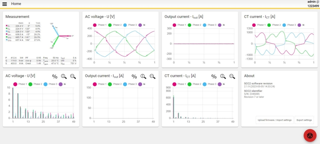
Once the new filters were installed a full commissioning was carried out on by our engineers along with a connection of a remote monitoring device as standard to provide remote access to the Active Harmonic Filter from any desktop PC.
Upon completion of the works, the new AHF lowered site’s average voltage distortion down from 6% to 2% across multiple harmonic ranges and corrected the Power Factor from 0.89 inductive to 0.99 inductive.
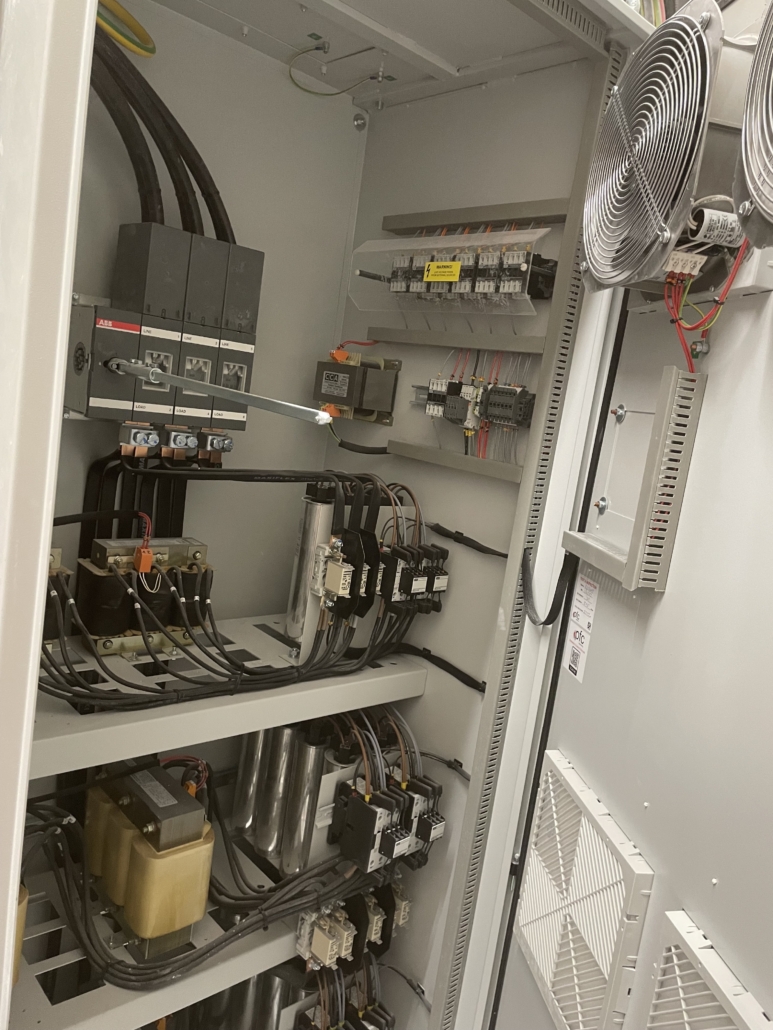
Original Power Factor Correction Equipment on site.
A large engine manufacturing plant that had multiple failures inside their panel-built Power Factor Correction unit including welded contactor coils, heat-damaged cabling and capacitor failures. Due to the age of the equipment and the wide range of failures, it was decided that an end-of-life replacement of all components would be required.
Load tests taken on-site showed that the full 300kVAr of the original install was not required and the site would operate with a healthy power factor of only 200kVAr. As such the units were rebuilt with 4 stages of 50kVAr detuned capacitor banks utilising the existing framework.
There are 2 supplies in the Switchroom each with its own PFC section so both sets were replaced with new equipment. The reduction in the total amount of kVAr installed in each unit also allows for better access during future maintenances as the LV panel has no rear access.
All the work was carried out by one engineer over 2days without any disruption to the site.
Above – Original 300kVAr PFC Equipment
Below – New 200kVAr PFC Equipment rebuilt in LV Panel
https://www.pfc-engineering.com/wp-content/uploads/2024/02/IMG_1379.jpg800600Ben Wallacehttps://www.pfc-engineering.com/wp-content/uploads/2021/10/PFC-Logo.pngBen Wallace2024-02-28 11:00:182024-02-09 15:44:51Rebuild of Panel Built PFC Equipment
Following an annual maintenance check at a large grain storage and drying facility found that there are high harmonic distortion levels on the sites load and as such the standard FS200 Power Factor equipment installed was now elevating the harmonics even more. As such a replacement fully detuned FSi200 Power Factor Unit was now required.
As the units output rating stayed the same all the original power cables were able to be re-used from the standard PFC unit along with the MCCB feeding the unit. This also meant all the work could be completed during normal working hours without the need for a shutdown.
Ventilation for the unit was also installed due to the heat produced from the reactors. An over temperature safety circuit was also installed as standard to cut the power to the relay should the heat in the unit reach an unsafe level.
After a full site load and power quality analysis, recommendations were made to this fencing manufacturer for the installation of a fully detuned Power Factor Correction unit.
This unit would be one of our new style FSi 400 Deep units and would include 8 stages of 50kVAr, each detuned by a 7% 189hZ reactor to help with harmonic distortion.
The new unit was close coupled to the main LV panel and connected directly to the bus bars due to the LV Panel having no spare ways. An 800MCCB was built into the PFC unit for isolating and fault protection.
The unit was positioned and fitted during normal working hours and then a shutdown of around 30 minutes was carried out at the end of the day for final connections keeping both install costs and disruption to the site down to a minimum.
https://www.pfc-engineering.com/wp-content/uploads/2024/02/IMG_2139-scaled.jpg25601920Ben Wallacehttps://www.pfc-engineering.com/wp-content/uploads/2021/10/PFC-Logo.pngBen Wallace2024-02-01 14:37:372024-02-09 15:41:40New FSi400 Unit Installed At Fencing Company
Working with one of our facility providers we were asked to carry out Power Factor services at several Courts around the UK. At one of the sites, it was found that the PFC capacitor banks had failed and the main MCCB had failed internally and required replacement.
A load survey was carried out as standard while carrying out the service and it was found that the site no longer required the full 300kVAr worth of correction and that smaller, more refined capacitor banks would benefit the site.
As such, it was decided that the original 630A MCCB would be replaced and reduced in size, along with a new 100kVAr SBA tray assembly, including all new 480V rated capacitors, soft switching contactors and sub fusing.
Due to the need to replace the Power Factors main MCCB, a full shutdown was required to remove and install the new main switch. This was done after hours to minimise any disruption to site staff.
The original capacitor banks and control relay were all removed during normal working hours and the new SBA tray was installed ready for the final connections during the scheduled shutdown period.
All the old equipment was removed by us and disposed of by PFC Engineering.
After being approached by a customer to review their site’s Power Factor following high reactive charges a desktop review of the site’s electricity bills and an on-site load survey it was found that significant savings could be made from installing some detuned PFC equipment.
Based on the half-hourly data provided, the following maximum demand load was recorded:
1764 kVA 1493.9 kW 0.847 PF 937.6 kVAr
We calculate that in order to improve the above PF to a satisfactory level of 0.966, approximately 540kVAr of detuned PFC would be required.
With the above 540kVAr of PFC in circuit, the following improved maximum demand conditions would result:
1545.9 kVA 1493.9 kW 0.96 PF 397.6 kVAr
Total Reduction in Maximum Demand: 218.1kVA (303Amps)
FINANCIAL SAVINGS
Based on the above, Sites Network Operators “Use of System” charges for supplies metered at high voltage and current site unit charges, we estimated that the above improved conditions would provide the following potential annual savings:
Transformer loss reduction: £1,473.90 + VAT (£0.155 x 9,509kWh pa)
Total Potential Annual Savings: £4,661.90 + VAT
Considering the above, we proposed the following:
The 540kVAr would be arranged in 2 x 270kVAr detuned PFC systems arranged in “Master-Slave configuration and connected via an existing 630Amp MCCB’s.
Since this supply has 2 transformer feeds (typically one on duty with a closed bus-coupler), a current signal will be taken from each of the transformer’s LV supply and connected via a summation CT within the Master PFC unit. This ensures that the PFC control will operate correctly, irrespective of transformer connection and bus-coupler status.
https://www.pfc-engineering.com/wp-content/uploads/2023/11/IMG_0331-scaled.jpg25601920Ben Wallacehttps://www.pfc-engineering.com/wp-content/uploads/2021/10/PFC-Logo.pngBen Wallace2023-12-14 10:30:362024-02-09 15:45:52Detuned PFC install at Major Chemical Distributor
Here are some examples of recent capacitor installations for drive motors.
Firstly, we have 2 22.3kVar ‘fixed’ C-Type PFC Units each connected to a 75kW 6-pole start/delta drive. These fixed style capacitor units work in line with the motor switching contactor so come into circuit whenever the motor comes online and then shuts off when the motor is stopped.
Above: PFC C-Type Fixed capacitor banks mounted on side of Motor control panel
Another example of a 22.3kVAr PFC unit connected to a 75kW 6-pole soft start drive, this time mounted in its own enclosure incorporating a rapid discharge circuit and timer all controlled by the soft start 24V run signal few via a relay circuit.
Above: T-Type style PFC unit conneted to Motor Control Panel
We may request cookies to be set on your device. We use cookies to let us know when you visit our websites, how you interact with us, to enrich your user experience, and to customize your relationship with our website.
Click on the different category headings to find out more. You can also change some of your preferences. Note that blocking some types of cookies may impact your experience on our websites and the services we are able to offer.
Essential Website Cookies
These cookies are strictly necessary to provide you with services available through our website and to use some of its features.
Because these cookies are strictly necessary to deliver the website, refusing them will have impact how our site functions. You always can block or delete cookies by changing your browser settings and force blocking all cookies on this website. But this will always prompt you to accept/refuse cookies when revisiting our site.
We fully respect if you want to refuse cookies but to avoid asking you again and again kindly allow us to store a cookie for that. You are free to opt out any time or opt in for other cookies to get a better experience. If you refuse cookies we will remove all set cookies in our domain.
We provide you with a list of stored cookies on your computer in our domain so you can check what we stored. Due to security reasons we are not able to show or modify cookies from other domains. You can check these in your browser security settings.
Google Analytics Cookies
These cookies collect information that is used either in aggregate form to help us understand how our website is being used or how effective our marketing campaigns are, or to help us customize our website and application for you in order to enhance your experience.
If you do not want that we track your visit to our site you can disable tracking in your browser here:
Other external services
We also use different external services like Google Webfonts, Google Maps, and external Video providers. Since these providers may collect personal data like your IP address we allow you to block them here. Please be aware that this might heavily reduce the functionality and appearance of our site. Changes will take effect once you reload the page.
Google Webfont Settings:
Google Map Settings:
Google reCaptcha Settings:
Vimeo and Youtube video embeds:
Other cookies
The following cookies are also needed - You can choose if you want to allow them:
Privacy Policy
You can read about our cookies and privacy settings in detail on our Privacy Policy Page.
We use cookies on our website to give you the most relevant experience by remembering your preferences and repeat visits. By clicking “Accept All”, you consent to the use of ALL the cookies. However, you may visit "Cookie Settings" to provide a controlled consent.
This website uses cookies to improve your experience while you navigate through the website. Out of these, the cookies that are categorized as necessary are stored on your browser as they are essential for the working of basic functionalities of the website. We also use third-party cookies that help us analyze and understand how you use this website. These cookies will be stored in your browser only with your consent. You also have the option to opt-out of these cookies. But opting out of some of these cookies may affect your browsing experience.
Necessary cookies are absolutely essential for the website to function properly. These cookies ensure basic functionalities and security features of the website, anonymously.
Cookie
Duration
Description
cookielawinfo-checkbox-advertisement
1 year
Set by the GDPR Cookie Consent plugin, this cookie is used to record the user consent for the cookies in the "Advertisement" category .
cookielawinfo-checkbox-analytics
11 months
This cookie is set by GDPR Cookie Consent plugin. The cookie is used to store the user consent for the cookies in the category "Analytics".
cookielawinfo-checkbox-functional
11 months
The cookie is set by GDPR cookie consent to record the user consent for the cookies in the category "Functional".
cookielawinfo-checkbox-necessary
11 months
This cookie is set by GDPR Cookie Consent plugin. The cookies is used to store the user consent for the cookies in the category "Necessary".
cookielawinfo-checkbox-others
11 months
This cookie is set by GDPR Cookie Consent plugin. The cookie is used to store the user consent for the cookies in the category "Other.
cookielawinfo-checkbox-performance
11 months
This cookie is set by GDPR Cookie Consent plugin. The cookie is used to store the user consent for the cookies in the category "Performance".
CookieLawInfoConsent
1 year
Records the default button state of the corresponding category & the status of CCPA. It works only in coordination with the primary cookie.
viewed_cookie_policy
11 months
The cookie is set by the GDPR Cookie Consent plugin and is used to store whether or not user has consented to the use of cookies. It does not store any personal data.
Analytical cookies are used to understand how visitors interact with the website. These cookies help provide information on metrics the number of visitors, bounce rate, traffic source, etc.
Cookie
Duration
Description
_ga
2 years
The _ga cookie, installed by Google Analytics, calculates visitor, session and campaign data and also keeps track of site usage for the site's analytics report. The cookie stores information anonymously and assigns a randomly generated number to recognize unique visitors.
_ga_FBPPGCCY4W
2 years
This cookie is installed by Google Analytics.
_gat_gtag_UA_40748982_1
1 minute
Set by Google to distinguish users.
_gid
1 day
Installed by Google Analytics, _gid cookie stores information on how visitors use a website, while also creating an analytics report of the website's performance. Some of the data that are collected include the number of visitors, their source, and the pages they visit anonymously.